Gas Hob Installation & Electric Hob Installation
The installation of all hobs is usually straightforward, requiring no more than the unit being fitted into a worktop space. In all cases, the cut-out aperture is specified in the user instructions. We do not recommend that apertures are cut into worktops on the basis of brochure specifications and that the installer checks the product before making the cut-out in the worktop; this can prevent potentially costly mistakes.
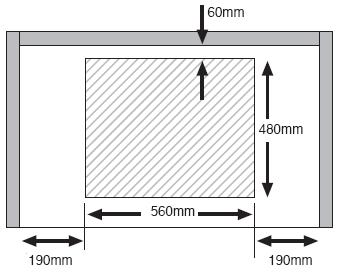
The following image shows the typical installation requirements, applicable to most hobs: -

Note that the cut-out sizes for each hob are shown in the instruction booklet and, in most cases, the CDA brochure or web site.
The distances vary between each product but the general requirements are as follows: -
- The distance between the hob and the back wall, when installed, must be 50mm or greater.
- The distance between the hob and adjacent vertical surface must exceed 150mm.
- The height between the hob and any extractor above it should be as detailed below.
Important!
The instructions provided with the hob will dictate the minimum height of any extractor to be fitted above it. The same information is provided with the extractor and unless specific exclusions are specified in the extractor instructions then the higher of the heights specified in the two instruction booklets must be used. In the case of gas appliances, failure to observe the correct installation requirements may lead to the installation being reported to RIDDOR and may delay any installation sign-off.
Since January 2008, it has been a legal requirement that gas hobs fitted in multi-occupancy dwellings or flats be fitted with Flame Supervision Devices. (Now applies to all properties)
Securing the Hob to the Worktop:
With most hobs a number of fixing clips are supplied to hold the hob on the worktop (some induction units are not provided with fixing clips). The fixing screws should be tightened evenly and preferably by hand; if power tools are to be used for this, ensure that they are set to a low torque setting.
Hobs should never be sealed to the worktop using silicone sealant. This can make it difficult to remove the appliance for repair and is unnecessary.
Induction Hob Ventilation:
Induction hobs require ventilation and are generally provided with cooling fans to prevent the internal electronics from over heating. It is important to consider this when installing any oven below the hob.
If an induction hob cuts out during use, then the most likely cause is inadequate ventilation. An error code is usually displayed and this is explained in the instructions provided with the hob.
Electrical Connection
One of the most common reasons for service intervention shortly after installation is due to poor electrical supply connection. Where an electric hob does not appear to work immediately following installation, it is highly likely that it has been incorrectly connected to the mains supply.
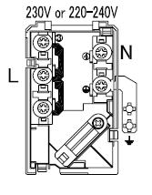
CDA products commonly use terminal blocks with brass bridging links included. It is important that they are used and correctly fitted. If not, localised terminal failure due to over-heating may result. An example of one such terminal block is shown below; these are typically seen on ceramic units: -

In this example, there are 3 live terminals linked together and a single neutral plus earth.
Note that some products have 3 live terminals and 2 neutrals
Note that some induction hobs are supplied with multi-core cables; the instructions supplied with these products provide all the information required for the correct connection to the mains supply.
The terminals for most ceramic and solid plate hobs are designed to be used with mains cable of cross-sectional area 2.5mm2. A larger sized cable may not fit. Where the rated input of a 4 or 5 zone electric hob (shown on the rating plate and in the instructions) is below 7.5kW, it is perfectly acceptable for a 2.5mm2 CSA multi-core cable to be used.
Under no circumstances should an electric hob (ceramic, induction or solid plate) be installed using a 13A plug or a 13A fused spur. All of these hobs should be installed using a dedicated cooker point.
If a single oven is to be installed to the same mains supply, then it should be provided with an appropriate fused spur, protected by an appropriate fuse.
Gas Connections
Gas hobs should be installed on rigid copper pipework and an isolation tap provided in a position which is accessible after installation. It is the responsibility of the installer to comply with all applicable gas regulations. Only a Gas Safe registered installer should connect any gas appliance to the supply.
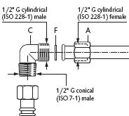
The most common installation issue is where a gas leak has been reported. Invariably, this is as a result of a gas leak at the elbow, where one or more of the unions has not been correctly assembled and tightened. The correct assembly is shown in the next image: -

Ensure all gas connections are sound after installation, using appropriate leak detection methods, but not a naked flame. Note that:
- The elbow (C) should be connected with the parallel thread connecting to the hob union (A), using the fibre washer (F)
- The tapered BSP thread should be connected to the copper supply pipework.


